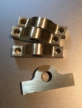
At least three bearing blocks are needed for supporting the worm gear. One on either side of the worm itself and one to support the handle end of the shaft. Depending on the distance from worm to the handle, making a fourth may be judicious. Consequently, four bearing blocks were prepared.
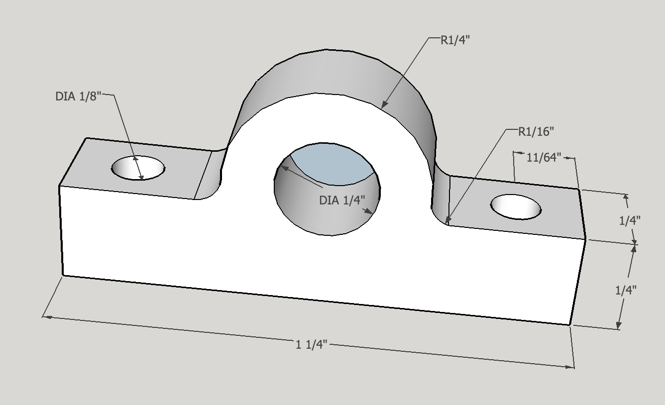
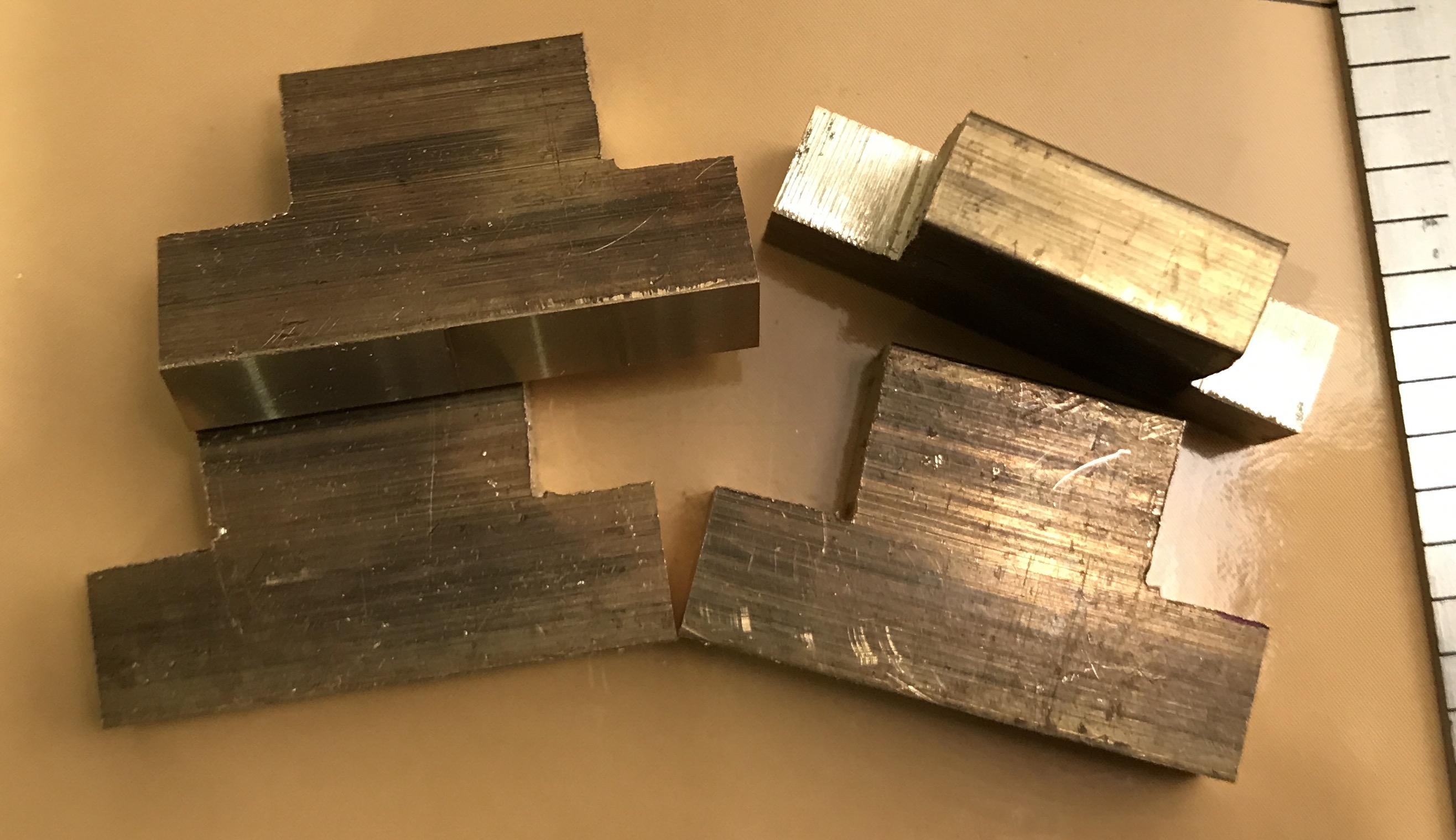
1/4" X 3/4" brass bar stock was selected. Four pieces were cut to approximately 1 1/4" with the hacksaw. The cut ends and one long side were cleaned up in the mill with the two bit cutter. Two corners (1/4" X 3/8") were removed also with the hacksaw. After coloring with a Sharpie the milled long side was placed on the granite (pseudo) surface plate and a line 5/16" high was scribed on the face. The horizontal center line was also scribed on the face. These two lines mark the bearing hole center.
The holes were drilled up to a letter "B" drill bit and then reamed with a 1/4" reamer. The holes not only fit the shaft of the worm, but also fit the pin in the center of the rotary table for the next operation.
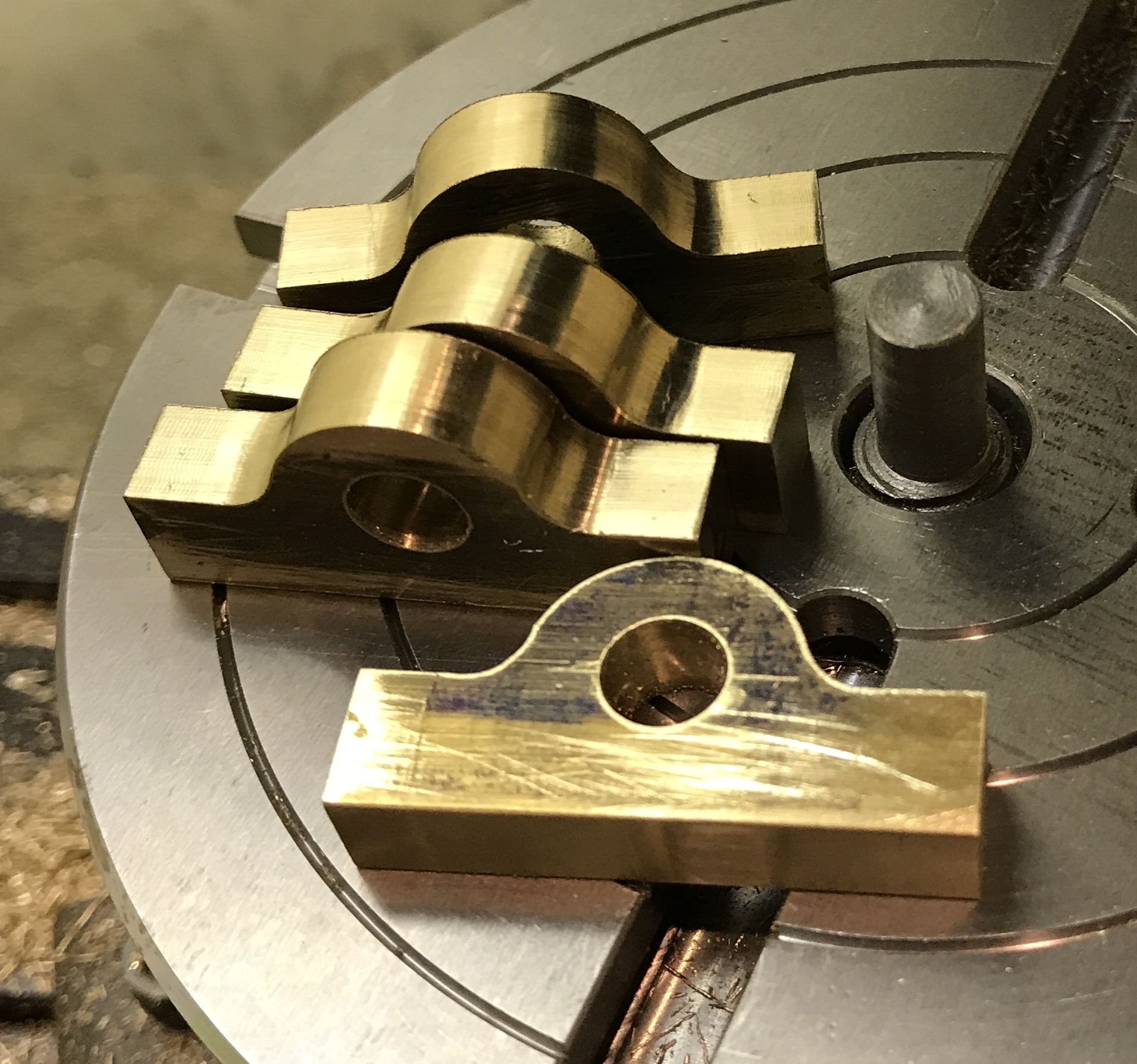
A rough cut part was placed over the pin in the center of the rotary table and clamped with two strap clamps. It was held up off the table with a scrap of aluminum. The pin was centered under the spindle and then the x-axis was locked. The table was moved off center and a corner of the part was "located" with the 3/16" end mill. The table was turned cutting the 1/4" radius from side to side. The end mill was rotated into the part at both ends creating slight depressions at each end of the round cut. About 0.015" of brass was removed in each pass. This was repeated with each of the four parts.
The "wings" of the parts then needed to be finished on the top side where they protruded beyond the depressions cut previously. This was done by replacing each part successively on the pin of the rotary table on the scrap aluminum with one clamp on the opposite end to the cutting. The part was aligned by eye using a straight edge pushed against it. Light passes of 0.005" were taken until the cut reached the bottom of the depression. The four finished parts (except for drilling the ends) are shown below.
The dental mirror came in handy to check the back side of the parts when cutting the ends so as to come out even with the 1/4" radius cut.
Drilling the through holes for the 4-40 screws was the next step. In order to best align the holes the vise was aligned to within 0.001" with the DTI. The parts were placed on a 1/4" shaft prior to placing in the vise and on a disk of sacrificial aluminum. The fixed jaw of the vise and the end of the workpieces were located. The holes were 1/8" in from the end and from the side. A center drill was used to start the holes and this was followed with a 0.140" drill bit. All holes in a row were drilled before switching to the other end. After drilling the front and back sides were sanded up to 600 grit paper to complete the job.